OxyProbe DO Sensors
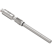
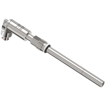
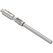
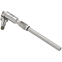
Broadley-James offers the widest range of autoclavable and steam sterilizable polarographic dissolved oxygen sensors available on the market today. Sensors are available in both 12 mm and 25 mm body diameters and in insertion lengths up to 420 mm. Connection options are the industry standard 4-pin D9 connector or Variopin in both straight and right angle formats. The new OxyProbe II incorporates an improved membrane design, increased signal stability, easier assembly and enhanced regulatory documentation.
Browse AllOXYPROBE DO SENSORS


Filter Results
OXYPROBE DO SENSORS FAQs
Why should DO sensors be calibrated after sterilization?
Calibration: To optimize the readings, dissolved oxygen probes should be calibrated in the process media, after sterilization. This is due to several factors:
- Sterilization could alter the sensor output. The tension of the membrane against the cathode is an important factor in the sensor signal. The high temperatures of sterilization may cause the membrane to stretch. Calibrating after sterilization will account for any possible change in the sensor’s output.
- Many bioprocess applications involve aerating or sparging the vessel while applying an over pressure to the tank. This overpressure may affect the readings if not taken into account during the calibration.
- Since the membrane permeability is slightly different in air than in water and the ambient relative humidity of air is usually less than 100%, air calibrations can differ from aqueous calibrations by a very small amount.
In summary, when measuring dissolved oxygen as % saturation, the calibration should be performed under process conditions to minimize error and maximize accuracy and reproducibility.
How should I install a DO Sensor?
A DO sensor must be at least 15° above horizontal to consistently function properly. DO NOT install DO sensors in a port perpendicular to the vessel wall. The liquid in the sensor contains small air bubbles. If not inclined slightly above horizontal, a bubble can adhere to the cathode where it will affect the sensor’s performance.
Why would I choose a longer sensor length?
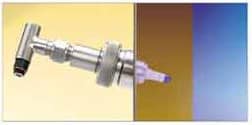
Sometimes the tank wall can become coated with a thick layer of viscous material that does not mix well with the rest of the media. If the pH sensing bulb of the sensor is located just a couple of inches inside the tank wall, the bulb might be smothered by this viscous layer. Subsequent pH readings may not be representative of the bulk of the media circulating in the rest of the tank. In the illustration at the right, the pH sensor's bulb is trapped in this slow moving viscous layer near the tank wall. The sensor is only measuring the pH of this layer.
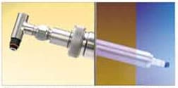
The solution to this problem described above is to choose a sensor and matching housing that extends further into the tank. This will position the pH sensing bulb away from the tank wall and place it closer to the circulating media further inside the tank. The subsequent pH measurements will be much more representative of the circulating media. In the illustration to the right, the sensor and housing protrude past the viscous zone and into the area of well stirred and circulated media within the production tank.
How do I change an OxyProbe II Membrane Cartridge?
 There are two distinct types of 12 mm DO sensor cartridges: one for the traditional style sensor (for example, OxyProbe D140) and one for the newer style OxyProbe II sensors. Please make sure you received
the right membrane cartridge for your particular sensor design. The old and new membranes are not interchangeable and cannot be installed on the wrong sensor type. However, once opened, they cannot be
returned or re-sold so be sure to check the box label before opening it. If you have any questions, feel free to call us at +44 (0) 1525 862518.
Important Notice:
The O2 electrolyte has an alkaline pH value of 13. Contact of electrolyte with the skin, especially the mucous membrane of the eyes, should be avoided. If such contact occurs, rinse the affected area thoroughly
with water. Get medical attention if adverse signs appear. An MSDS is available for download from our website if desired. Great care should be exercised when handling the sensor and changing the membrane. The internal glass cathode is very fragile and any impact can cause a crack or fracture which can permanently damage the sensor.
Great care should be exercised when handling the sensor and changing the membrane. The internal glass cathode is very fragile and any impact can cause a crack or fracture which can permanently damage the sensor.
Because contact with the electrolyte is very likely during exchange of electrolyte or membrane body, the use of protective gloves and eyewear is recommended.Membranes are typically replaced after a single use in high-value processes, or after multiple uses in R&D, university, PD labs, etc. How many uses you might expect depends upon the process conditions. Visit our website FAQ section for more detailed information.
Membranes are typically replaced after a single use in high-value processes, or after multiple uses in R&D, university, PD labs, etc. How many uses you might expect depends upon the process conditions. Visit our website FAQ section for more detailed information.
Membrane Replacement Instructions
To replace the used membrane with a new one, or to remove, clean, and re-install the existing membrane, please follow these procedures:
- 1. Unscrew the cap sleeve from the shaft and carefully remove it from the sensor. Place the sensor down nearby in a safe place where it will not roll off or bump into anything that might damage the fragile glass tip of the cathode.
- Usually the membrane cartridge remains in the cap sleeve when the sleeve is removed from the sensor body. Tip it over and pour out the old electrolyte solution (remember it is pH 13). Carefully push on the flat face of the membrane with your finger or thumb to dislodge it from o-ring holding it in place within the cap sleeve. The cartridge should slide free of the cap sleeve.
- If re-using the old membrane, rinse it out with DI water using a squeeze bottle or other device to ensure all of the old electrolyte and byproducts are removed. Refill the cartridge slightly with OxyProbe electrolyte solution. Rinse it around and pour it out to flush out any remaining DI water.
- Check the o-ring on the sensor body, just above the threads where the cap sleeve attaches. If installing a new membrane, replace the o-ring with the one supplied with the membrane. If it is a re-use, inspect the o-ring and replace if necessary.
- Fill the membrane halfway with electrolyte solution, and give it a “tap” or “flick” of your fingernail to make any large bubbles rise to the top. *
- While holding the sensor in a vertical position, slide the membrane cartridge over the cathode assembly. The excess electrolyte will be displaced and this should be patted dry with a paper towel, kimwipe, etc.
- Take the steel cap sleeve and carefully slide it over the membrane cartridge, threading it onto the body until it is completely flush with the body.
- Rinse off any excess electrolyte that may have spilled, and dry the sensor with a paper towel, kimwipe, etc.
- Each time the membrane is changed the sensor should be polarized and calibrated before use. See the instruction manuals for your particular sensor and instrument, or visit our website “Documents” link.
* NEVER fill the membrane with electrolyte while it is lodged inside the cap sleeve. This causes excess electrolyte to be captured inside and can result in the rupture of the membrane during the autoclave cycle.
How do I choose the correct membrane cartridge for my dissolved oxygen (DO) sensor?

How do I select a sensor for benchtop vessels?
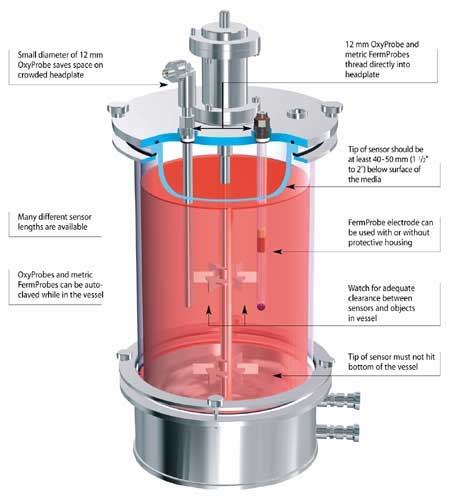
Typically a benchtop application is less than 5L, and uses a glass vessel or flask. Usually the entire vessel can be placed or wheeled into an autoclave for sterilization prior to a run. Not only is there a range of different vessel sizes used in benchtop bioprocess applications, but also the volume of the media in the vessel will often change during the process. Accordingly, the sensors for benchtop vessels are available in a wide variety of lengths. The operator must choose a sensor length that ensures the sensor tip is submerged at all times during operation. Some sensor models have been configured to thread directly into the headplate and various access ports found on small vessels. Detachable cables and other design features allow these products to withstand the demands of autoclaving requirements.
How Do I test My OxyProbes?
Purpose for test:
Dissolved oxygen membrane cartridges contain an oxygen-permeable, polymer membrane, which is impermeable to liquid. Improper storage or accidental handling of the DO sensor or membrane cartridge can damage the polymer membrane. A hairline scratch, slight abrasion or any tear of the polymer membrane may render the cartridge inoperable. Often the damage may not be visible to the naked eye.
STEP 1. VISUAL EXAMINATION
Remove the membrane cartridge from its storage vial or from the dissolved oxygen sensor. Be careful not to scratch or abrade the polymer membrane portion of the cartridge.
Visually inspect the outer surface polymer membrane for scratches, scars, abrasions or tears.
STEP 2. PLUNGER “READY” POSITION
Install the nosepiece onto the syringe and retract the plunger of the membrane tester to the “ready” position as shown below.

STEP 3. MEMBRANE CARTRIDGE INSTALLATION
Insert the tip of the membrane tester into DI water to lubricate it before installing the membrane cartridge as shown below. Avoid excessive force.

STEP 4. APPLYING PRESSURE TO THE MEMBRANE CARTRIDGE
Slowly compress the plunger until the membrane cartridge bladder slightly protrudes from the thumb and forefinger slots of the cartridge housing.

STEP 5. MEMBRANE CARTRIDGE TEST
Place membrane tester with the membrane cartridge into a beaker of DI water as shown. Make certain the front of the membrane cartridge is completely submerged.
STEP 6. ASSESSING DAMAGED MEMBRANE CARTRIDGES
While maintaining a slight pressure on the plunger to keep the bladder extended, slowly rotate the test assembly in the water.
Look for any signs of air bubbles which indicate a damaged membrane or bladder. Refer to the two illustrations for typical examples of air leaks found when the membrane has been damaged.
- NOTES:
A good membrane will not permit any air to escape from the membrane cartridge when this test is properly performed. - Replace cartridges which show any signs of air leakage, whether flowing from or clinging to the surface of the polymer membrane.
- New membrane cartridges should always be kept in their individual storage vials until required for service. Avoid unnecessary handling. Membrane cartridges installed on a dissolved oxygen sensor should be protected during non-use.
Testing the Cathode
PROCEDURE:
Refer to drawing below. Using a multimeter with the test leads attached to as shown, V ohms and COM connect one lead to a small piece of aluminum foil and the other lead to the WHITE (cathode) lead of the sensor cable. Gently touch the tip of the platinum cathode to the aluminum foil being careful not to damage the surface of the cathode. With the multimeter selector switch in the ohms position, the readout should indicate a direct short or "zero" ohms. This measurement verifies proper electrical continuity between the tip of the platinum cathode, the connectors, and the cable.
RESULTS:
A reading which is significantly different than "zero" ohms could indicate a faulty cable, cable connector, sensor connector, and/or internal fault to the cathode. Replace the cable assembly and repeat the test measurement. If the correct reading is not achieved, replace the sensor connector. If the correct reading is not achieved after these two steps, the sensor should be returned to the factory for further service.

PROCEDURE:
Refer to drawing below. Using a multimeter with the test leads attached to V ohms and COM as shown, connect one test lead to the RED (anode) lead of the sensor cable. Gently touch the tip of the other test lead to the outer surface of the silver anode. With the multimeter selector switch in the ohms position, the readout should indicate a direct short or "zero" ohms. This measurement verifies proper electrical continuity between the anode, the connectors, and the cable.
RESULTS:
A reading which is significantly different than "zero" ohms could indicate a faulty cable, cable connector, sensor connector, and/or internal fault to the cathode. Replace the cable assembly and repeat the test measurement. If the correct reading is not achieved, replace the sensor connector. If the correct reading is not achieved after these two steps, the sensor should be returned to the factory for further service.

PROCEDURE:
Refer to drawing below. Using a multimeter with the test leads attached to V ohms and COM as shown, connect one test lead to the BROWN (RTD) of the sensor cable and the other test lead to the BLACK (RTD) of the sensor cable. With the multimeter selector switch in the ohms position, the readout should indicate between 27.0 k ohms to 22.0 k ohms at room temperature (20 to 25°C) or other appropriate resistance value depending upon the ambient temperature. This measurement verifies the internal thermistor is functioning properly.
RESULTS:
A reading which is significantly different than the values given above could indicate a faulty cable, cable connector, sensor connector, and/or internal fault with the thermistor. Replace the cable assembly and repeat the test measurement. If the correct reading is not achieved, replace the sensor connector. If the correct reading is not achieved after these two steps, the sensor should be returned to the factory for further service.
What is the sensor measuring?
OxyProbes measure the partial pressure of oxygen. The partial pressure of Oxygen is dependent on the mixture of the gases and the pressure inside the vessel. Uncompensated variations in pressure can be a significant source of error. When reading % saturation or ppm, the operating pressure of the vessel should be entered into the transmitter if the process pressure is not the same as the calibration pressure. This number should account for elevation above sea level and/or any overpressure on the vessel. The pressure can be entered in mm Hg, inches Hg or bar.